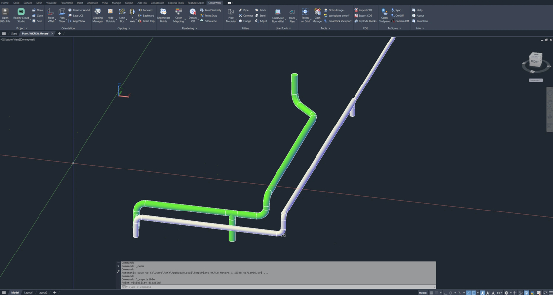
本指南介绍如何使用 Pipe Modeler 工具提取管段并创建 T 形分支连接。
Prerequisite: 如需完整的流程背景与结果,请查阅本系列的前述指南:
练习数据
Exercise CAD file (.dwg format)
隔离要提取的管道
在提取管道几何形状之前,让我们先定义感兴趣区域,并调整颜色映射设置,以便轻松识别点云中的管道。
管道对象分类
- 在 Rendering 选项卡上,选择 Color Mapping。
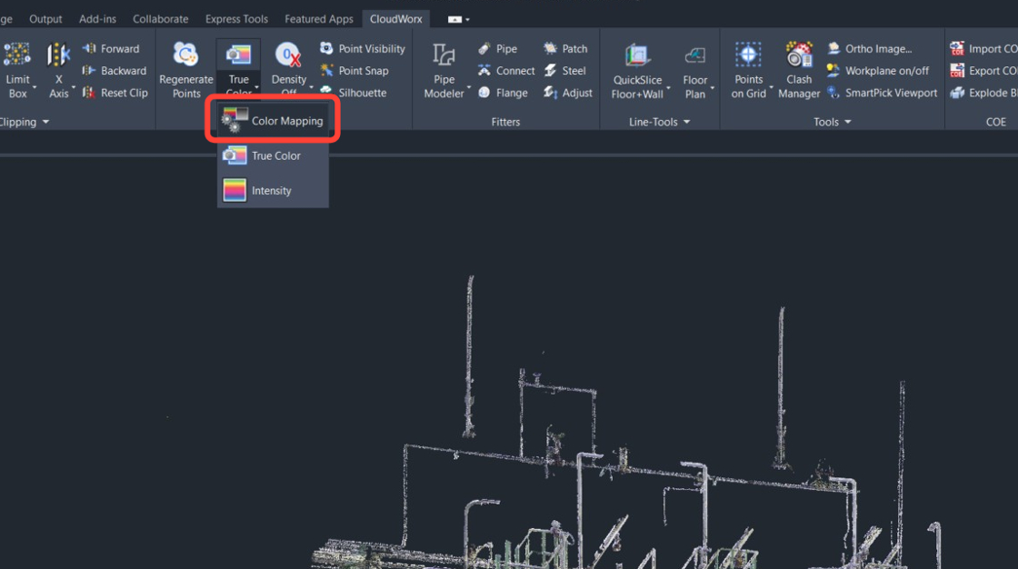 2. 在 Point Cloud Color Mapping 对话框中,将 Global Color Mapping 设置为 Classification 并单击 Apply。
.jpeg) 3. 单击 Class Visibility。
3. 单击 Class Visibility。
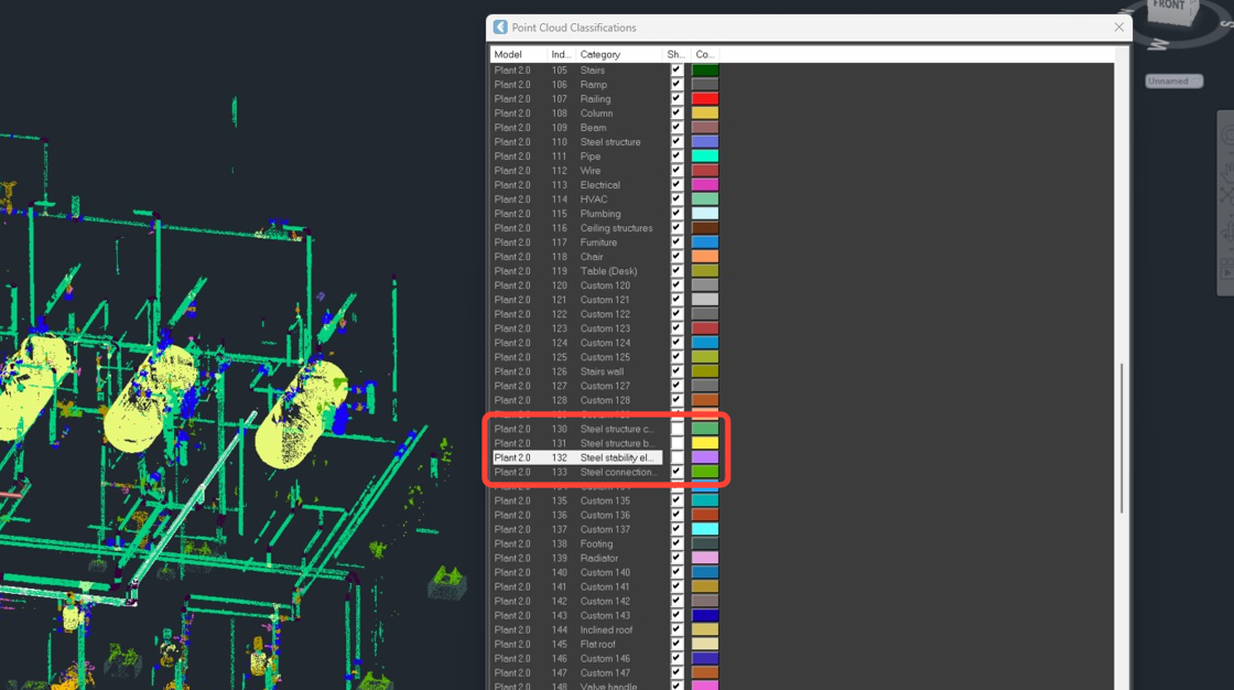
.jpeg) 4. 在分类表中,查看各个类别,并取消勾选下列类别,使管道及其连接在点云中更加醒目。
- 1 Unclassified(未分类)
- 130 Steel structure column(钢结构柱)
- 131 Steel structure beam(钢结构梁)
- 132 Steel stability element(钢结构稳定构件)
- 133 Steel connection element(钢结构连接构件)
4. 在分类表中,查看各个类别,并取消勾选下列类别,使管道及其连接在点云中更加醒目。
- 1 Unclassified(未分类)
- 130 Steel structure column(钢结构柱)
- 131 Steel structure beam(钢结构梁)
- 132 Steel stability element(钢结构稳定构件)
- 133 Steel connection element(钢结构连接构件)
 5. 关闭分类表和 Point Cloud Color Mapping 对话框。
使用 Fence 裁剪感兴趣区域
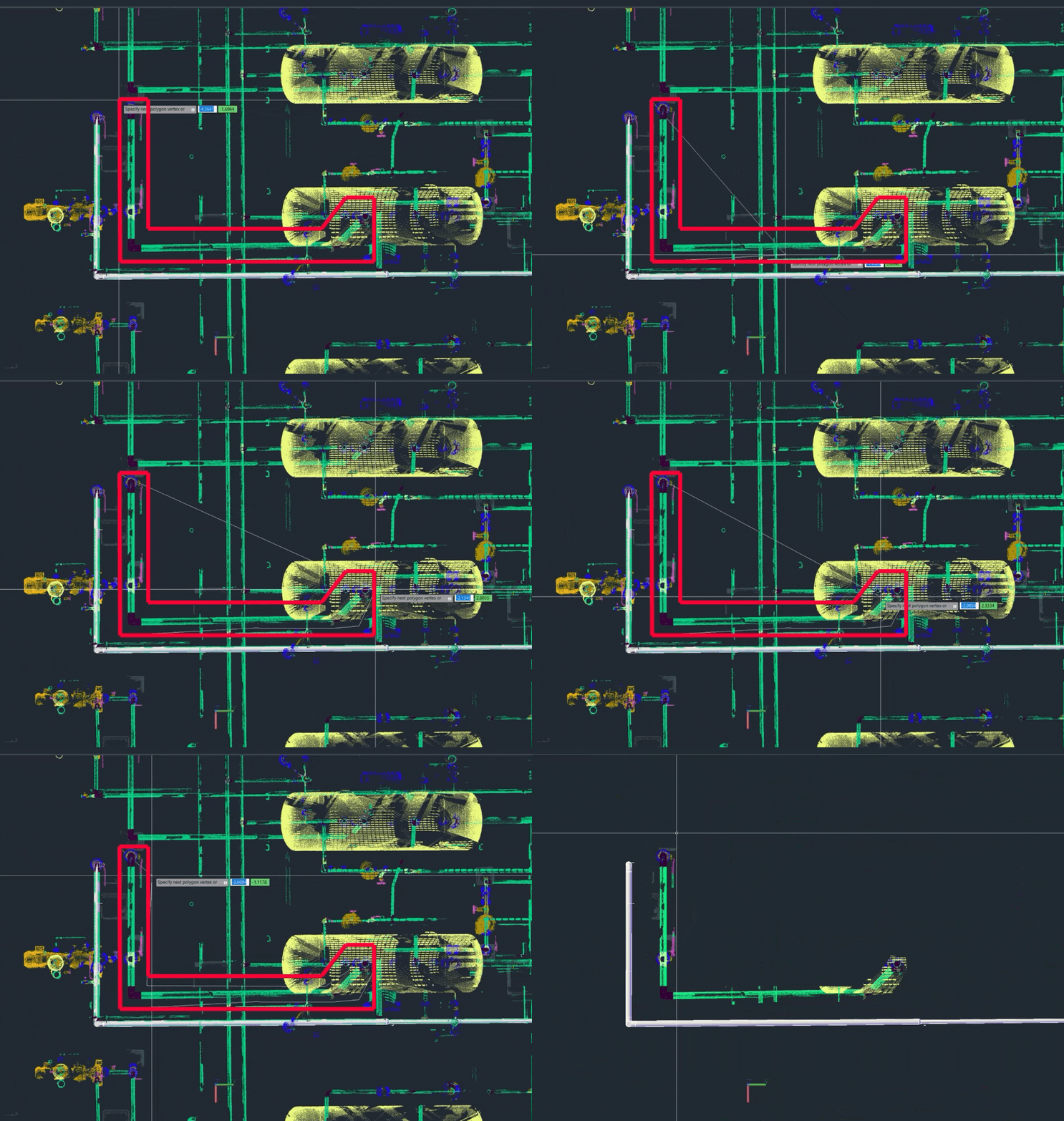
- 导航到 Clipping | Hide Outside,或在命令行中输入 CWHIDEOUT。然后,在命令行中选择 Polygon,或输入 P 并按 Enter,切换到多边形围栏模式。
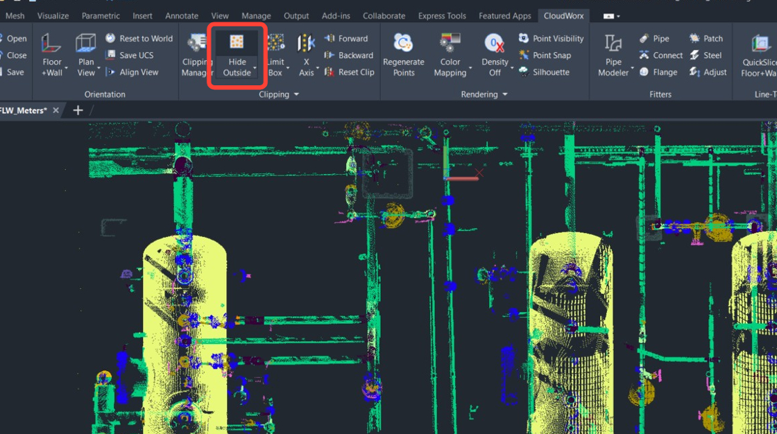 2. 围绕要提取的管路绘制一个围栏。完成后,按 Enter。
使用 Pipe Modeler 工具
本部分流程介绍如何使用 Pipe Modeler——一款半自动工具,可根据所选参数提取管道几何形状。
提取管路几何形状
首先,让我们提取前面步骤中隔离出来的管路段。
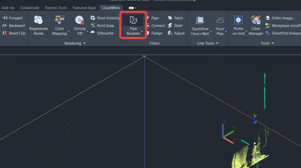
- 转到 Fitters 并单击 Pipe Modeler。
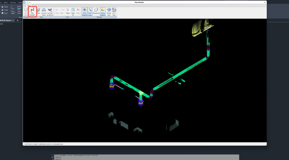
 2. Pipe Modeler 将在新窗口中打开。在 Tools 面板中单击 Pipe Modeler。
 3. 启动 Pipe Modeler 工具后,Ribbon 会更新并显示更多选项。在 PipeSystemTool 面板中,选择以下设置:
1. 选中 Use Catalog 复选框,然后选择所需的目录。在本示例中为 ISO_GR1_PIPE-METRIC。
2. 将 Bend Ratio 设置为 1.3。
3. 选中 Detect Elbow 复选框。
4. 选中 Detect Branch 复选框。
3. 启动 Pipe Modeler 工具后,Ribbon 会更新并显示更多选项。在 PipeSystemTool 面板中,选择以下设置:
1. 选中 Use Catalog 复选框,然后选择所需的目录。在本示例中为 ISO_GR1_PIPE-METRIC。
2. 将 Bend Ratio 设置为 1.3。
3. 选中 Detect Elbow 复选框。
4. 选中 Detect Branch 复选框。
 4. 单击管路的起点。
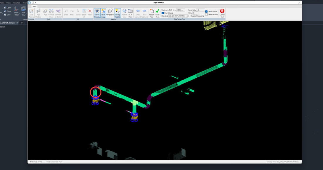 5. 检查建议的目录拟合结果,然后单击 OK。Pipe Modeler 会延伸管路,直到需要提示为止。
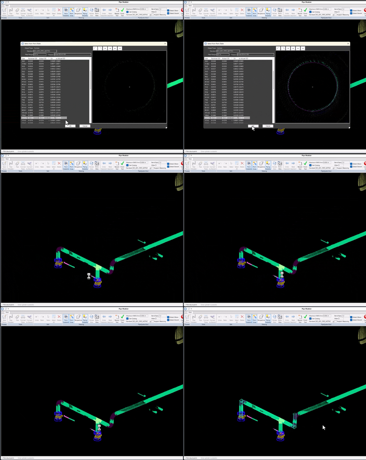 6. 单击下一段管道。这样可为 Pipe Modeler 提供下一个提示,以继续提取几何形状。
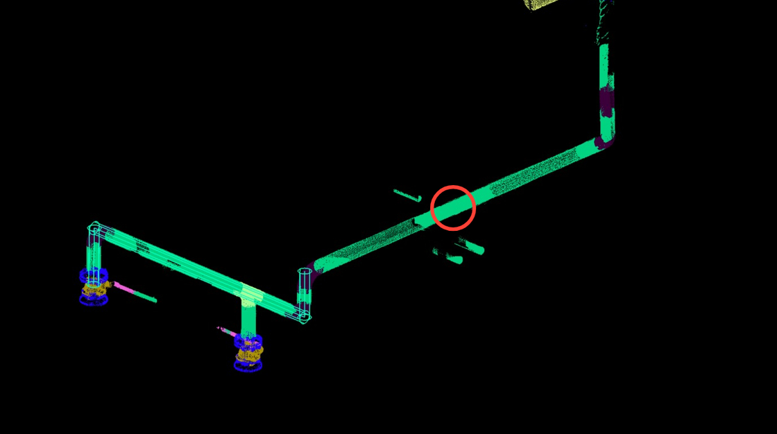
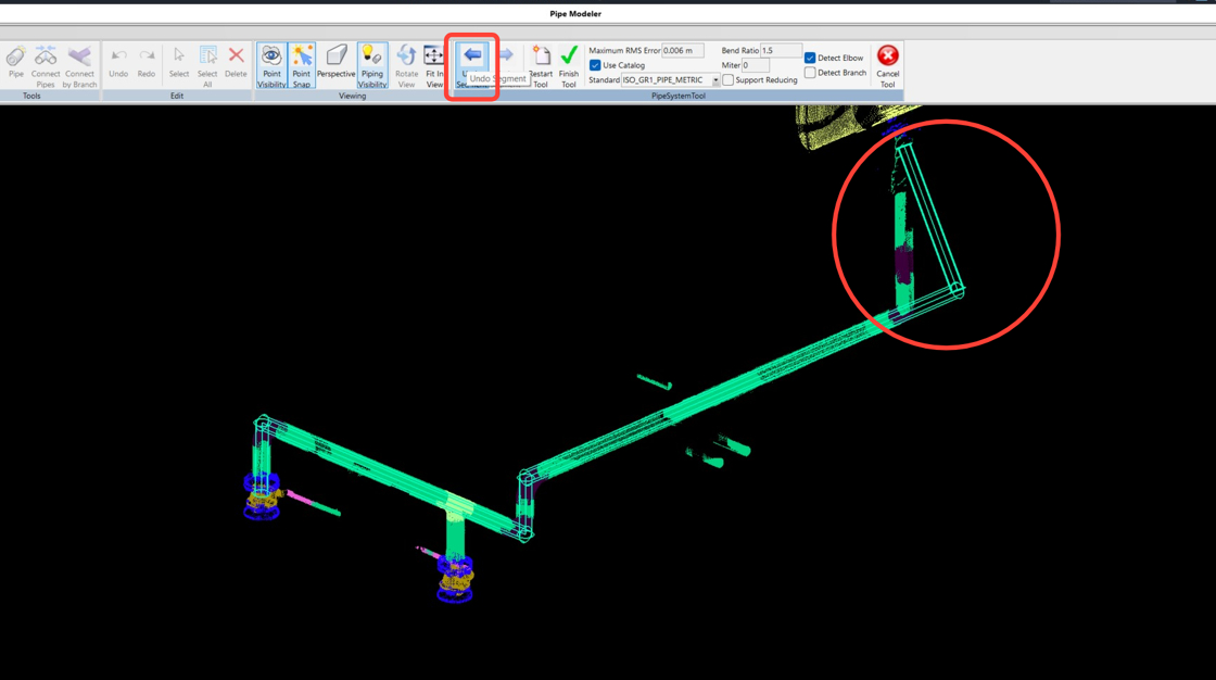
如果 Pipe Modeler 延伸管道过长,请单击 Ribbon 上的 Undo Segment 按钮。
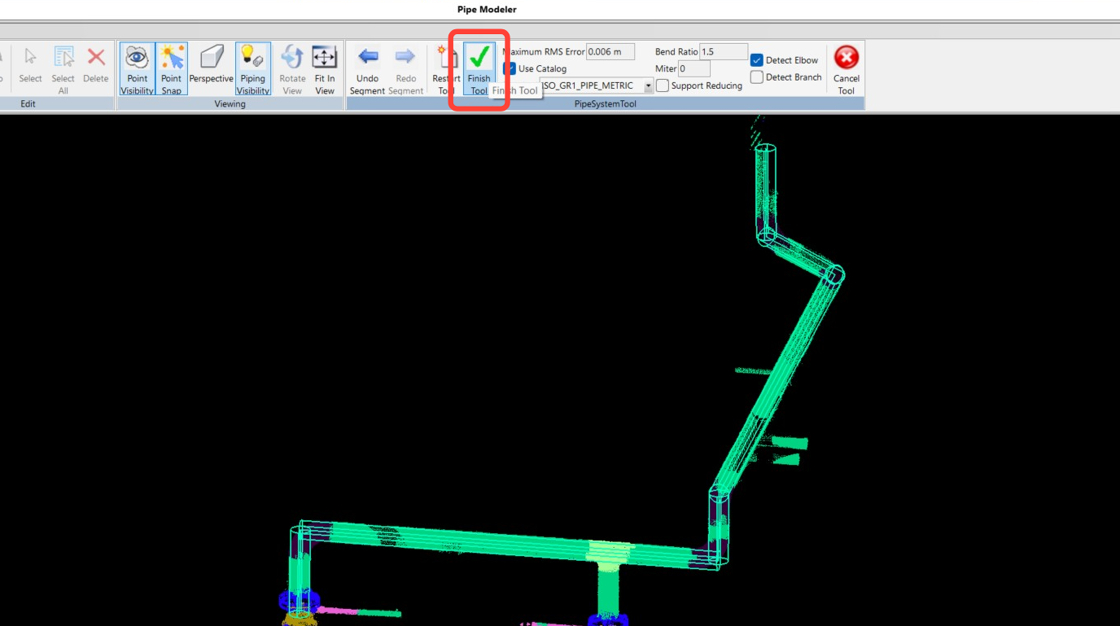
- 继续单击其余直管段,以完成整条管路。完成后,单击 Finish Tool。
添加 T 形分支连接
接下来,让我们使用 Pipe Modeler 功能,通过 T 形分支连接把已提取的管段连接起来。
- 在 Pipe Modeler 中,转到 Tools | Pipe。
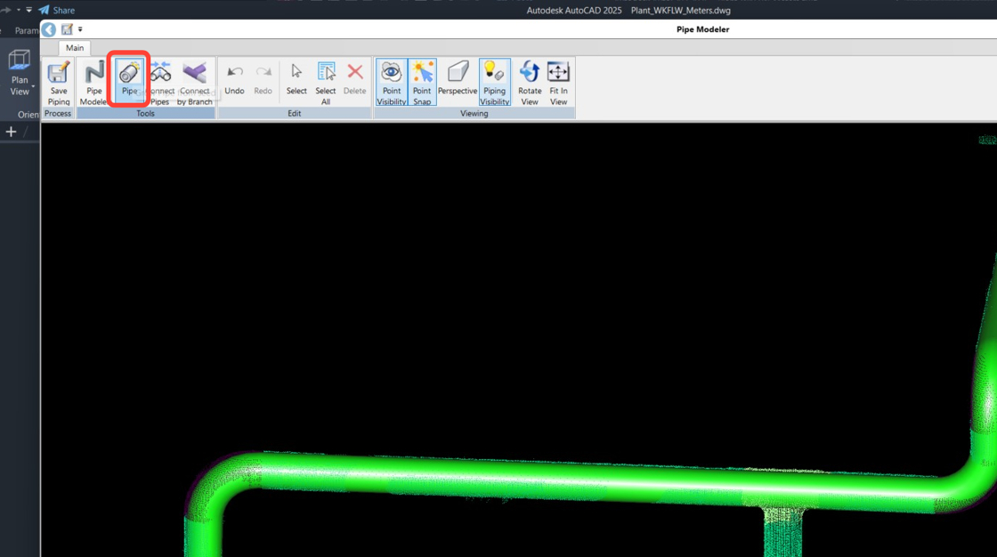 2. 单击分支管段以提取其几何形状。
.jpeg) 3. 检查建议的目录拟合结果,然后单击 OK。
4. 管段提取完成后,单击 Cancel Tool 接受结果。
3. 检查建议的目录拟合结果,然后单击 OK。
4. 管段提取完成后,单击 Cancel Tool 接受结果。
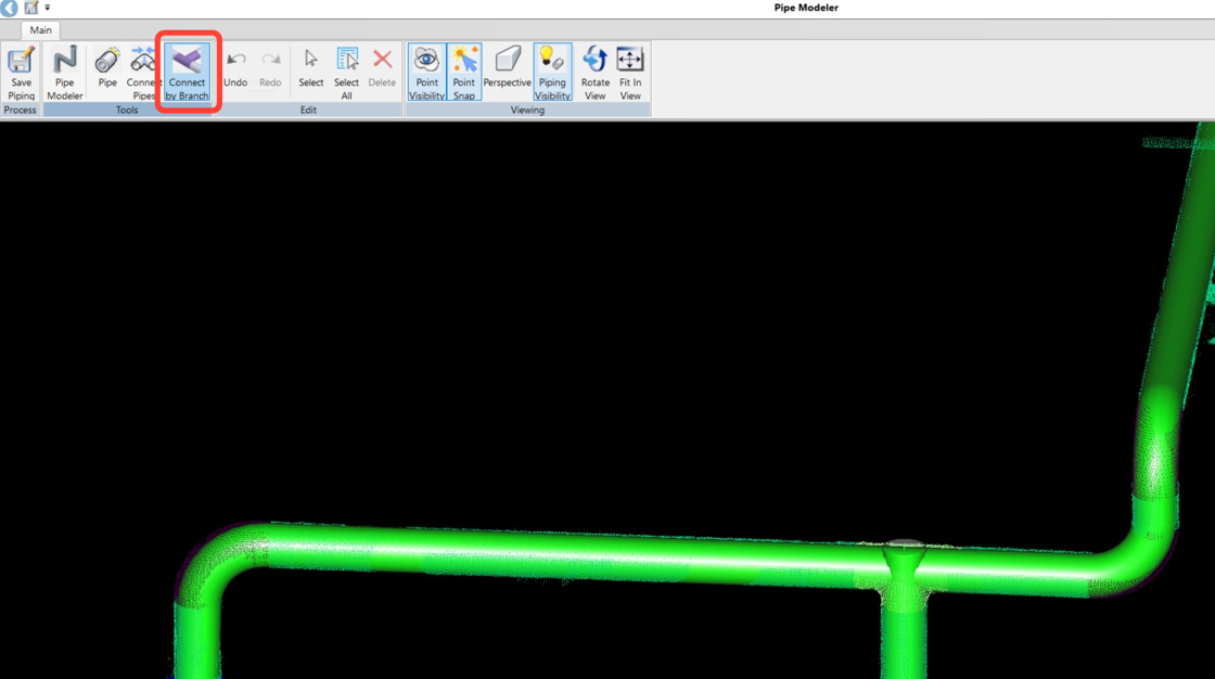
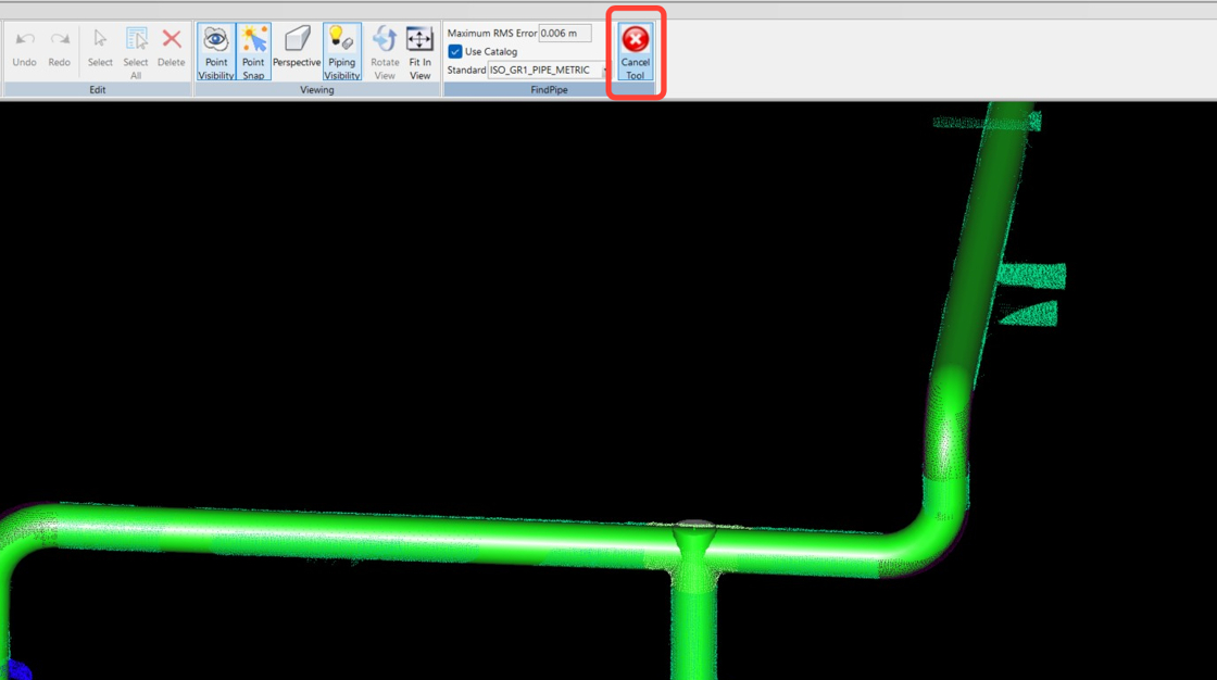 5. 现在,在 Tools 面板中单击 Connect by Branch。
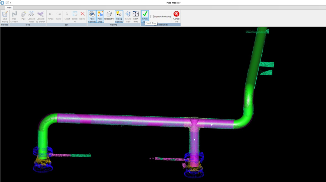
 6. 选择主管系统和刚创建的管段。选中后,两者都会变为洋红色,表示可以连接。然后单击 Finish Tool 接受结果。
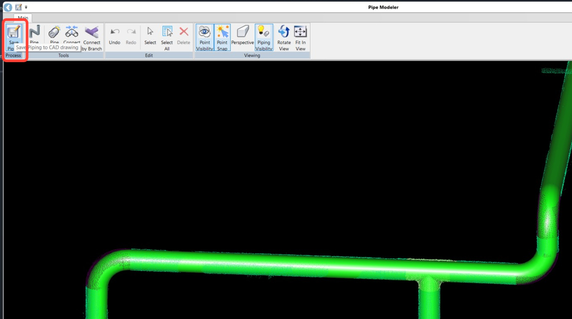
 7. 在 Process 面板中,单击 Save Piping,将创建的管路导出到 CAD 窗口中。然后关闭 Pipe Modeler。
 8. 在 ModelSpace 视图中检查结果:
1. 转到 CloudWorx | Rendering 并关闭点可见性。
2. 切换到 Visualize 选项卡,并将视图模式设置为 Conceptual。
8. 在 ModelSpace 视图中检查结果:
1. 转到 CloudWorx | Rendering 并关闭点可见性。
2. 切换到 Visualize 选项卡,并将视图模式设置为 Conceptual。